Iowa Industrial Moderated Newsgroup For Surplus Equipment > Food Service
> Microwaves
> New
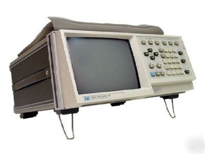
> Hewlett packard 1630G logic analyzer with nist cert.
Hewlett packard 1630G logic analyzer with nist cert.
Logic Analyzers Specifications
16 words, HP 1630A/D, 1631A/D; 16 or 1024 words, HP 1630G
all patterns within a label set may be marked or separately displayed
for each of three ORed clocks, select either or both edges; separate edges of one clock may be selected for multiplexed modes
25 MHz for single edge of single clock; 20 MHz for any combinations of ORed clocks and edges
master clock must follow slave clock by at least 10 ns and precede next slave clock by at least 50 ns.
to 59,999; applies to final sequence term only
width of analyzer by 16 words; trace until "equal to" or "not equal to" with each compare word matched to all 1024 words in memory; compare words may contain "don't care" items
the compare file is the full 1024 states of memory
10 ns to 500 ms in 1, 2, 5 sequence
min detectable glitch, 5 ns width at threshold; with glitch detection on, number of timing channels is halved
20 ns to 1 ms in 1, 2, 5 sequence with accuracy ± 20% or 15 ns, whichever is greater; glitch or edge ANDed with asynchronous pattern
approx. 218 times the sample period, to 9999 s max
time between dual cursors (x and o) displayed to accuracy of one sample period
X1 to X40 in 1, 2, 4 sequence; standard display shows entire 1 k memory at X1
ANALOG ANALYSIS MODE (HP 1630G)
1:1, 10:1, or 50:1 probe attenuation factors may be entered to scale the HP 1631A/D to input voltages at the probe tip
Analog-to-digital conversion (ADC) resolution
± LSB, which is ± 1.6% of full-scale
± 5.25ns, 20% to 80% of full-scale
channel 1, channel 2, or external trigger input
rising or falling edge may be selected for any source
5 ns to 500 ms in a 1, 2, 5 sequence
125 ns to 500 s full-scale (10 divisions)
Time-interval measurement accuracy (equal rise and fall times): single-shot, ± 1.5 ns for 5 ns sample period, ± 1 sample period for sample periods of 10 ns or greater; continuous, ± .15 times sample period, based on 100 averages
equals trigger plus delay; tracepoint can be delayed from 0 to about 260k sample periods after the trigger
two channels are digitized simultaneously
Digitizing technique (real-time digitizing)
all data points are digitized at equal selectable increments in time on each acquisition
selectable, 2 samples/second to 200 megasamples/second
1024 samples, 6 bits/channel, 2 channels; up to 1000 samples are used for display; magnifier allows full-screen display from 1000 samples to 25 samples; the entire 1024 sample record can be accessed via HP-IB and HP-IL.
INTERACTIVE STATE/TIMING/ANALOG ANALYSIS MODE
analog, timing, and state data acquisition occur simultaneously
either of the three analyzers can be master while the remaining two are slave
the waveform analyzer and the timing analyzer can be simultaneously armed by the full data indexing capability of the state analyzer
the waveform analyzer and the state analyzer can be simultaneously armed by the full indexing capability of the timing analyzer
the timing analyzer and the state analyzer can be simultaneously armed by the full analog indexing capability of the waveform analyzer
analog, timing, and state acquisition data can be correlated in time
timing channels can be displayed on the same screen with analog channels; the tracepoint and time/div are common to timing and analog in this display mode, and set by the timing analyzer
SOFTWARE PERFORMANCE ANALYSIS AND OVERVIEW MODES
all 1024 events/samples for any label group can be displayed as a chart of order of occurrence by magnitude; max and min vertical limits are user-specified
measures time between start and stop events defined for up to eight time ranges
histogram; min, max, average, and last time reading; total elapsed time; number of samples
for four-bit label group, 250 ns or 0.1% of reading, whichever is greater
sampled occurrence count of events in a label group for up to eight total user-defined ranges or values
Time-positional histogram (HP 1630G only)
shows the number of occurrences of an event over time. A time unit is defined, and the analyzer counts the occurrences of a specified event in that time unit. The measurement can be repeated for up to 1023 equal-sized time units.
Typical accuracy of first time unit
-250 ns to +500 ns, ±0.01% of specified width
Typical accuracy of subsequent time units
Linkage histogram (HP 1630G only)
Max number of definable events
two cursors (X and O) are provided for making voltage and time measurements on displayed waveforms. Both absolute and differential values are provided for voltage measurements. Dual cursor time measurements can be made between two points on the same waveform or between two points on different waveforms.
X to O cursor statistics are provided for continuous voltage and time measurements: max, min, mean and standard deviation. Single cursor voltage statistics can be obtained between two points on the same waveform or between two points on different waveforms (time only).
both X and O cursors can be uniquely specified with respect to the tracepoint or acquisition start, by selection of channel 1 or 2, rising or falling edge, voltage level, hold or delay time.
100k ohm, ± 2% shunted by approximately 5 pFat at probe body
Minimum input overdrive (above pod threshold)
250 mV or 30% of input amplitude, whichever is greater
± -9.9 V to +9.9 V in 0.1 V increments
channel 1, channel 2, external trigger
1 megaohm, ± 2% shunted by approximately 14 pF
up to eight state, up to 16 timing, user-defined, five-character labels may be assigned bit patterns in any configuration up to 65 (HP 1630G) bits/label. Bits may be used in more than one label and need not be contiguous.
all labels with four bits or less allow mnemonics to be assigned to specific patterns. Primary use is to identify such functions as read, write, opcode, etc.
up to sixteen module starting locations may be specified, allowing trigger parameters to be based on module names, plus an offset value.
a 24-hour clock prints out the time of data collection on all stored records.
provided in the format display for identifying active inputs
Non-volatile memory (HP 1630G)
the HP 1630G has 8k of EEPROM for internally storing a disassembler. One setup configuration of the instrument can also be stored.
An HP-IB connector, along with an eight-position switch, is located on the rear panel. Five positions are used to determine "talk-only" for hardcopy and system controller modes.
An HP-IL connector is located on the rear panel for interfacing
All instrument configurations and acquisition data may be remotely programmed via the HP-IB (IEEE-488) or HP-IL.
One BNC output is located on the rear panel with a TTL output. High is 2 V into 50 ohms; low is 0.4 V into 50 ohms. The BNC can be programmed from the keyboard to provide the following signals: pulse on state tracepoint, high until state tracepoint, low until state timing pattern, probe compensation (HP 1631A/D), and positive edge on analog trigger (HP 1631A/D). A second BNC is located on the rear panel to provide +5 V for the HP 10269B general-purpose probe interface.
up to 95% relative humidity at +40°C
vibrated in three planes for 15 minutes each with 0.3 mm excursions, 5 to 55 Hz.
115/230 Vac, -22% to +10%; 300 ? max; 48-66 Hz
190 X 426 X 447 mm (7.5 X 16.8 X 17.6 in)
One operating manual, one 2.3 m (7.5 ft) power cord, plus the following probes