Iowa Industrial Moderated Newsgroup For Surplus Equipment > Industrial Machine Repair
> Components
> New
> Bcp 420B-33ST laser transmitter & 320A optical receiver
Bcp 420B-33ST laser transmitter & 320A optical receiver
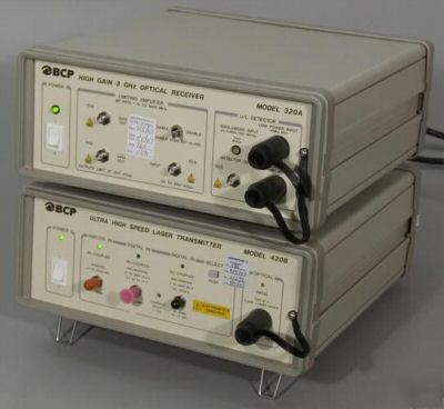
BCP (Broadband Communication Products), now JDS Uniphase 420B-33ST 2.5 Gb/s Ultra High Speed Laser Transmitter and 320A-33ST High Gain 3 GHz O/E Optical Receiver for 1550 nm Wavelength
Comes with what you see in the pictures. If you don't see it, you probably wont get it.
Specifications are from a BCP/JDS Uniphase and may vary slightly due to upgrades, options, or revisions this unit may or may not have.
The units are Intel surplus. They power up but we do not have the ability to formally test them. Guaranteed non DOA.
Link to the 320A Manual: BCP/JDS Uniphase 320A O/E Receiver Manual
The Transmitter's Serial Number Tag Reads:
The Receiver's Serial Number Tag Reads:
* Detector bandwidth DC 3 GHz
* Limiting amplifier included
* No gain or offset adjustments needed
* O/E conversion for transmitter testing
420B Transceiver Key Features:
* SONET/SDH compliant from OC-1 to OC-48 and STM-1 to STM-16.
* Optically isolated, temperature controlled DFB laser source.
* Analog and digital modulation inputs. Front panel selectable.
* Digital: DC to over 2.5 Gb/s.
* Analog: 0.1 to over 2500 MHz.
* Insensitive to digital input data patterns.
* Adjustable laser bias control to set digital extinction ratio.
* Universal optical connector with all popular adapters.
* +1 dBm peak output power, digital mode.
* -2 dBm average output power, analog mode.
The receiver detects and converts optical signals into electrical signals for the purpose of transmitter waveform analysis and testing, including error rate testing. It is optimized for analysis of high-speed, low-level optical signals from single-mode fiber sources. The high bandwidth (3 GHz) and high gain (2500 V/W) enable detection and analysis up to 2.5 Gb/s signals at levels down to below -30 dBm. The receiver is also equipped with a high-level input port for direct connection of laser sources at power levels up to +3 dBm without overload. The Model 320A 3 GHz O/E Receiver is the one solution that provides users with a low-cost, high-quality instrument for optical eye pattern analysis and testing at low to high power levels.
The receiver consists of a 3 GHz bandwidth optical-to-electrical (O/E) converter (1100 to 1600 nm) and a 3 Gb/s limiting amplifier. The detector out port for the O/E converter is DC coupled and automatically nulled to < +/- 100 µV DC. The nulling is automatically performed when the receiver does not have an optical input.
420B Transceiver Description:
The Model 420B Laser Transmitter is a very high speed, optically isolated and thermally stabilized fiber optic signal source designed for general laboratory use. The bench top instrument is fully connectorized for both RF inputs and optical output, and is AC line powered for any line source from 100 to 240 VAC. The unit accepts digital or analog input signals for direct modulation to beyond 2.5 Gb/s, with analog bandwidth over 2.5 GHz. The 420B generates a fiber-coupled optical output which can be used for testing detectors, receives, or any other component requiring temperature controlled, stable and flexible DFB laser optical source.
The 420A meets all applicable SONET/SDH standards from 51.84 Mb/s to 2.488 Gb/s (Reference Bellcore GR-253-CORE and ITU G.957 specifications), making it ideal for production receiver or system compliance proof-of-performance testing. The transmitter will also find application as either an analog or digital optical source in critical fiber optic link applications.
In the digital mode, both DC and AC-coupled digital inputs are front panel selectable. The DC-coupled digital input permits the user to operate completely independent of data pattern effects. The DC-coupled digital input will accept any ECL-level input pulse pattern, ranging from a DC level to isolated sub-nanosecond pulses, including continuous or burst mode formats. The AC-coupled digital input enables the user to interface with alternative non-ECL digital signal sources with widely varying DC logic levels.
The AC-coupled digital input also provides a mode with the lowest possible source-generated jitter. The AC logic threshold on the 420B digital input is front panel adjustable in the AC-coupled digital input mode to enable the user to optimize output pulse width and jitter for specific applications. The DFB laser bias point is rear panel adjustable within a limited range for extinction ratio and waveform control.
In the analog mode, the laser output is set between -3 and 0 dBm, and the AC-coupled analog input signal is routed directly to the laser through a termination and surge protection circuit. The optical modulation index is settable by input level from 0% to 80% minimum. This operating mode is highly useful for testing the linear bandwidth of detectors and detector-receiver combinations to beyond 2.5 GHz.
A universal optical connector interface on the front panel permits the optical connector to be user-changeable. Simple screw-on connector adapters for all industry-standard connector types are available. This connector also allows easy optical cleaning without removing the instrument cover. When the instrument is not in use, the permanently attached dust cap simply snaps in place over any type of adapter.
320A Performance Specifications:
High Power Optical Input: 1.0 mW (0 dBm) maximum
Low Power Optical Input: 200 µW (-7 dBm) maximum
Bandwidth (-3 dB): DC to 2.5 GHz minimum, 3.0 GHz typical
Maximum Conversion Gain1: 2000 V/W minimum, 2500 V/W typical. For lower power input; reduces as average input power increases.
Wavelength: 1200 to 1600 nm; InGaAs APD detector
Fiber Interface: 9/125 µm single-mode
Optical Input Connector: Diamond universal screw-on adapter
Input Optical Return Loss: 30 dB minimum, 1310/1550 nm
Low Power Input: 100 nW (-40 dBm)
High Power Input: 2000 nW (-27 dBm)
Polarity: Non-inverting (high input = high output)
DC Offset, Detector Out: Automatically nulled to < +/- 100 µV DC; automatic nulling is enabled when optical input power is removed
Overload Indicator (Flashing Red LED): Alarms at approximately 0.2 mW to indicate possible output overload distortion
Limiting Amplifier Input: 1.0 V peak-to-peak (pp) maximum
Bit Rate3: 0.01 to 2.5 Gb/s minimum, 3.0 Gb/s typical
Gain3: 24 dB minimum, 26 dB typical
Rise/Fall Times: 150 ps maximum, 20 to 80%, when in limiting region with 50 ohm termination
Input: 10 dB minimum, frequency < 2 GHz
Output: 10 dB minimum, frequency < 2 GHz
Output Amplitude: 0.45 Vpp minimum, 0.60 Vpp typical when in limiting region with 50 ohm termination
Input Level for Full Limiting: 30 mVpp minimum, 500 mVpp maximum
1: Gain self-adjusts to protect the sensitive avalanche detector.
2: The minimum detectable signal is the minimum optical input power required for unity output peak-to-peak signal-to-root-mean-square (RMS) noise ratio, measured in the full detector bandwidth.
3: Below limiting, the amplifier performs as a normal linear amplifier. Response is not guaranteed in the non-limiting linear region.
320A Receiver General Specifications:
Input Voltage: 100 to 240 VAC, 50 to 60 Hz
Power Consumption: 25 W maximum
Electrical Input Connectors: Female, SMA
Dimensions: 10.13" W x 4.54" H x 10.39" D (25.7 x 11.5 x 26.4 cm)
Operating Temperature: 10°C to 40°C
Storage Temperature: -20°C to 70°C
Humidity: 95% RH from 10°C to 40°C non-condensing
420B Transceiver Performance Specifications:
Limiting Values: Inputs exceeding these limits may cause permanent damage.
Digital Input (AC-Coupled): 2.0 Vpp, maximum
Digital Input (DC-Coupled): -4.5 V minimum to 0.0 V maximum
Analog Input (AC-Coupled): 2.0 Vpp, maximum
Digital Input: AC-Coupled Electrical
Bit Rate: 50 to 2500 Mbps, minimum, typically 3000 Mbps
Pulse Pattern: 40 to 60% ones density, 50% for optimum performance
Input Amplitude: 0.70 to 1.50 Vpp for fully-limited optical output
Input Impedance: 50 ohms AC-coupled through 0.1 µF
Digital Input: DC-Coupled Electrical
Bit Rate: 50 to 2500 Mbps, minimum, typically 3000 Mbps
Pulse Pattern: No constraints. All zeroes, all ones, or any other pattern, including burst-mode patterns.
Maximum: No limit, DC-coupled
Minimum: 0.4 nsec, maximum. For full peak amplitude output
Logic Levels: Any standard ECL: High = -900 mV (typical), Low = -1700 mV (typical), Threshold = +1.3 V +/- .2 V. 10K, 10KH, 100K, Si or GaAs IC/ASIC. Front panel adjustable threshold.
Input Termination: 50 ohms to -2.0 VDC, Standard ECL termination
Digital Output: Optical (for either AC or DC-coupled digital inputs)
Extinction Ratio: 8.2 dB, min (CAL Mode), Variable (UNCAL mode). Typically > 10 dB. Rear panel adjustable.
Polarity: Non-Inverting, electrical input high = optical output high
Eye Mask: Conforms to Bellcore GR-253-CORE and ITU G.957 requirements with 20% mask margin. Conformance guaranteed at OC-1 through OC-48 (SONET) and STM-4 through STM-16 (SDH)
Peak Coupled Power (fiber): 1.3 mW (+ 1 dBm), minimum. 9/125 µm single-mode fiber
Relative Intensity Noise (RIN): -135 dB/Hz, maximum. Typically < - 145 dB/Hz, measured in optical high state at 1 GHz into ORL > 25 dB
Jitter Generator: 0.05 UI pp, maximum, 0.005 UI rms, maximum. Measured per GR-253 and ITU G.958, 12 KHz - 20 MHz filter, SONET/SDH pattern.
Center Wavelength Option: 1550 nm (+/- 20 nm)
Spectral Widths (modulated at 2.5 Gbps): 0.3 nm maximum at -3 dB (typically 0.2 nm), 1.0 nm (maximum) at -20 dB (typically 0.8 nm)
Sidemode Suppression Ratio: 33 dB, minimum. Typically < 35 dB (2.5 Gbps)
Analog Input: AC-Coupled Electrical
Frequency Range: 0.1 to 2500 MHz, minimum. Usable frequency range.
Input Level: 1.0 vpp, typical. 2.0 vpp, maximum. For 0.8 peak modulation index.
Input Impedance: 50 ohms, AC-coupled. Return loss > 12 dB at 1 GHz.
Average Optical Power (fiber coupled): 0.63 mW (-2.0 dBm) minimum. 9/125 µm single-mode fiber
Frequency Response: 0.1 to 2500 MHz (minimum), -3 dB points (electrical)
Relative Intensity Noise (RIN): -135 dB/Hz, maximum. Typically < -145 dB/Hz. Measured at 1.0 GHz into ORL > 25 dB
Polarity: Inverting, Electric input high = Optical output low
Spectral Widths (modulated at 1.25 GHz): 0.3 nm (maximum) at -3 dB, typically 0.2 nm. 1.0 nm (maximum) at -20 dB, typically 0.8 nm
Sidemode Suppression Ratio: 33 dB, minimum. Typically < 35 dB (1.25 GHz modulation)
420B Transceiver General Specifications:
AC Power Requirements: 100 to 240 VAC, 50-60 Hz
Electrical Input Connectors: Female, SMA
Optical Output Connector: FC/PC
Temperature Range: 0°C to 40°C operating, -10°C to 70°C storage
Dimensions: 10.13" W x 10.39" D x 4.54" H (25.7 cm x 26.4 cm x 11.5 cm)
Certifications & Conformance:
* USA: This product conforms to DHHS Regulations 21 CFR, Subchapter J and IEC 825-1, Class 1 laser product
* CSA: This product has been model certified (No. LR102161) by the Canadian Standards Association (CSA). Conforms to CSA Specification No. 1010.
* CE Mark: This product is in conformity with Directive 89/336/EEC based on test results using harmonized standards in accordance with Article 10(1) of the Directive.
For More Pictures Please Click the Following:
* Picture 2 - Front View (320A Receiver)
* Picture 3 - Front View (420B Transmitter)
* Picture 4 - Back View (320A Receiver)
* Picture 5 - Back View (420B Transmitter)
* Picture 6 - Serial Number Tag (320A Receiver)
* Picture 7 - Serial Number Tag (420B Transmitter)